
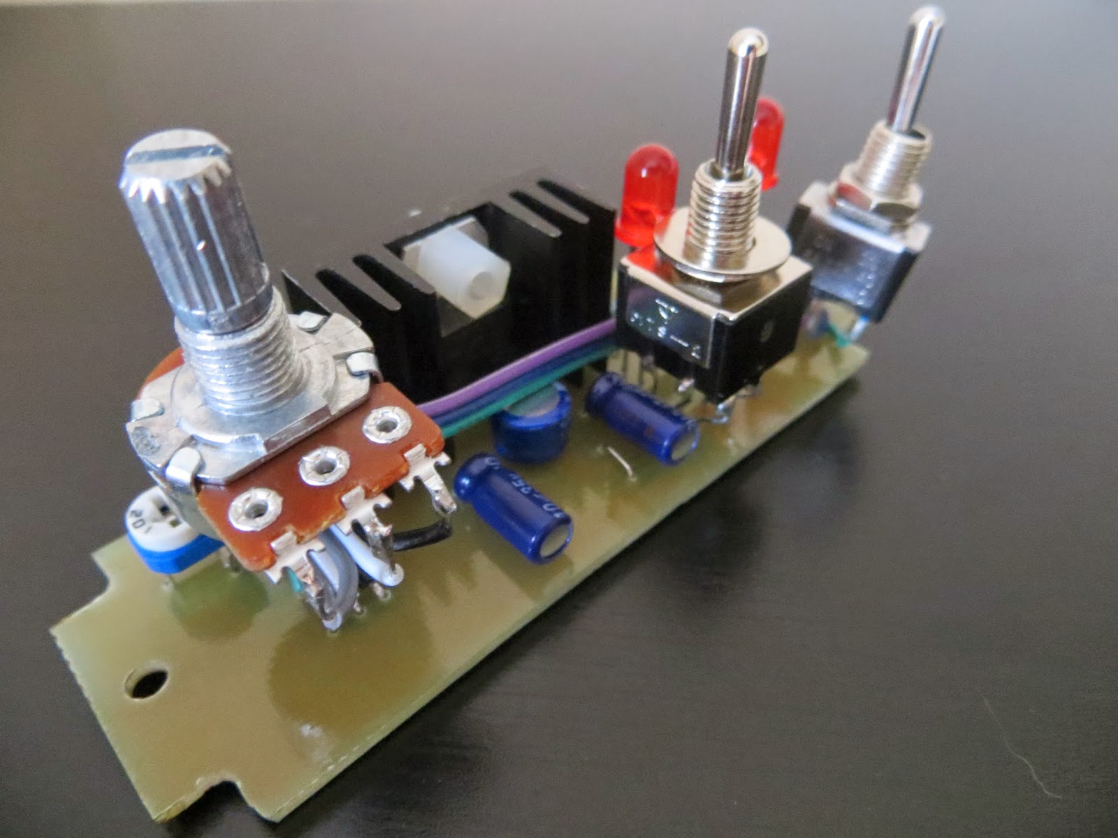
So, two switches, a knob and two output posts. Correct, but this thing has three operating modes, one of which has two selectable 'sub-modes' if you will. The modes are selected via the three way toggle switch and are described below.
Mode 1: Output OFF.
Whilst ever there is an active power supply entering the unit the 2nd LED will be illuminated, but the 1st one (left-most) will remain off. The first LED is therefore my output ON/OFF indicator.
Mode 2: Variable/Preset.
Using the LM317, which is an adjustable voltage regulator, the voltage can either be adjusted using the external potentiometer, or set at a preset voltage determined by an internal trimpot. This one is set internally to 5V. This option is selectable via the first toggle switch (again, leftmost).
Mode 3: Regulator Bypass.
Here we have straight up voltage goodness flowing out of those banana posts with zero regulation. The reason for this is that as I'm only using a 9V wall power supply at the moment, when I need 9V for my pedal projects, the LM317 falls short as it drops around 1.25/1.5 volts.
Also, whatever the mode, the power entering the box is being filtered through a simple circuit with reverse polarity protection added too.
Now that's all explained, I'll explain why there is going to be a 2nd version of this thing.
Overall, the design is perfectly fine and suits my needs well. But there is a blaring issue and almost luckily this unit actually only works 2/3's. I say luckily because I have to remake it once over anyway so this gives me ample opportunity to revise it slightly.
The problem is that if I'm using some logic stuff, such as a CD74HCT4066/max Vcc 7V, and I switch the mode switch from off to on, I could quite easily send the full input voltage to the chip frying it. To combat this I'm going to install a 'not-so-high-voltage-but-high-enough-to-fry-voltage' banana post next to the one already installed, so that once Mode 3 is engaged the output switches from one post to the other, safeguarding the low voltage chips from a zingy death.
As I said above, this unit only works 2/3's anyway as the bypass mode doesn't fully isolate the input voltage from part of the regulator circuit, causing a drop in voltage through a potential divider.
So yeah, another post soon with more pictures and less text about the second version.
Oh, and there will be an Instructable on this too!


0 comments:
Post a Comment